O-RAN Architecture
The disaggregation of the monolithic basestation into open, multi-vendor, software-defined functional units (RU/DU/CU) plus a programmable control layer (the RICs) where third-party apps — including ML — steer the radio network in near-real-time.
What · How · Why
What it is
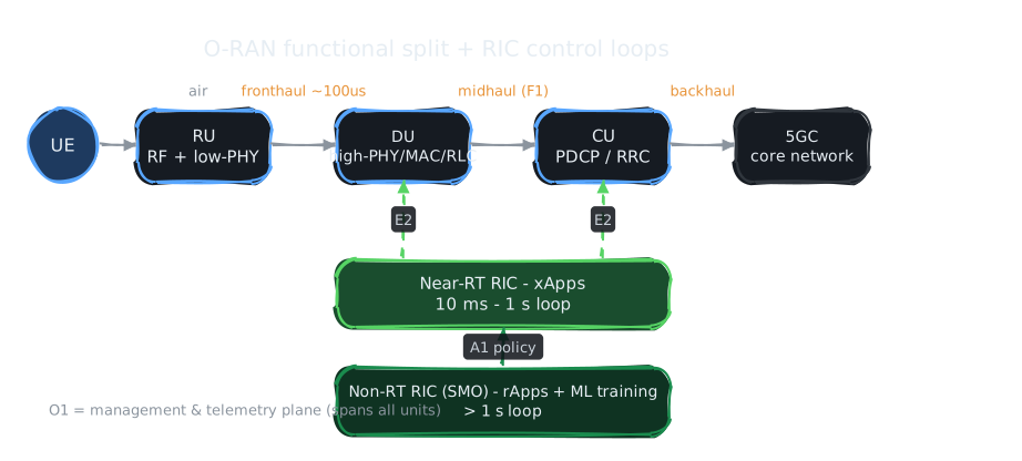
O-RAN takes the classic single-box basestation (the gNB) and slices it into three units connected by open, standardized interfaces: the RU (radio), DU (real-time baseband), and CU (packet processing & connection control). On top sits the RIC — a control layer that runs apps (xApps and rApps) to optimize the network. The whole thing is meant to run as cloud-native software on commodity hardware.
How it works
The RAN signal pipeline is cut at two points chosen by latency budget. The RU does RF and low-PHY at the cell site; the DU does high-PHY/MAC/RLC under hard real-time; the CU does PDCP/RRC and can be centralized in a datacenter. The near-RT RIC observes DU/CU over the E2 interface and issues control on a 10 ms–1 s loop; the non-RT RIC trains models and pushes policy via A1 on a >1 s loop.
Why it matters
It breaks vendor lock-in (mix-and-match RU/DU/CU), enables RAN-as-software (K8s, CI/CD, commodity x86/GPU), and — critically for this KB — opens a sanctioned hook to insert ML control loops into a live cellular network without waiting on a vendor. The RIC is the doorway through which AI enters the RAN.
Round 1 — Mental Model
The pre-O-RAN gNB is a sealed appliance: radio, baseband, and control welded together over proprietary interfaces from one vendor. O-RAN unbundles it into a kitchen brigade. The RU is the line cook at the pass, who must move in microseconds. The DU is the sous-chef coordinating the real-time line (scheduling who gets airtime each slot). The CU is the head chef handling slower, higher-level decisions (session setup, mobility). The RIC is the restaurant manager standing back, watching all the telemetry and handing down adjustments — the near-RT RIC tweaks the line mid-service, the non-RT RIC rewrites the menu between services. The open interfaces are the standardized tickets that let you swap any cook for one from a different agency.
Round 2 — Internal Mechanics & Mathematical Model
The functional split, formally
A "split" is a cut point in the L1/L2/L3 protocol stack that decides which functions stay at the cell site (RU/DU) and which centralize (CU). The dominant choice is the 7.2x intra-PHY split: iFFT/FFT and cyclic-prefix stay in the RU; the rest of PHY moves to the DU. The split is governed entirely by the fronthaul bit-rate it produces.
Formal definition (CPRI vs eCPRI fronthaul rate). A fully centralized PHY (the old "split 8" / CPRI) transports raw IQ samples. Its rate is independent of user traffic:
\[ R_{\text{CPRI}} = N_{\text{ant}} \cdot f_s \cdot 2 \cdot b_{\text{IQ}} \cdot \eta_{\text{cw}} \]where \(N_{\text{ant}}\) is antenna ports, \(f_s\) the sample rate, the factor 2 is I and Q, \(b_{\text{IQ}}\) bits per sample, and \(\eta_{\text{cw}}\) the line-code/control overhead (e.g. \(10/8\) for 8B/10B). For a 100 MHz, 64-port massive-MIMO cell this lands in the tens-to-hundreds of Gb/s — and crucially it scales with antenna count, not user data, which is why CPRI does not survive massive MIMO.
The 7.2x split moves the FFT into the RU so only post-FFT, used subcarriers cross the fronthaul:
\[ R_{7.2x} \approx N_{\text{layers}} \cdot N_{\text{sc}}^{\text{used}} \cdot \frac{1}{T_{\text{sym}}} \cdot 2 \cdot b_{\text{IQ}} \]Now the rate scales with spatial layers (≈ rank), not physical antennas, decoupling fronthaul from the MIMO array size. This is the entire economic argument for the 7.2x split.
Latency budget as a hard constraint
HARQ (hybrid ARQ) forces a closed retransmission loop between UE and DU. The fronthaul one-way latency must satisfy:
\[ T_{\text{fh}}^{\text{RTT}} = 2\,\frac{d_{\text{fiber}}}{c/n} + T_{\text{proc}} \;\le\; T_{\text{HARQ}} \]With fiber index \(n\approx 1.47\), light covers ≈ 5 µs per km round-trip. The eCPRI fronthaul budget is on the order of ~100 µs one-way, which caps DU–RU fiber distance to roughly 20 km. This single inequality is why the DU cannot be arbitrarily centralized.
Complexity / placement analysis
Why centralize the CU but not the DU? Because their workloads have different time-criticality and different statistical multiplexing gain. DU scheduling runs per-slot (every \(2^{-\mu}\) ms with numerology \(\mu\)) — placing it remotely violates the HARQ budget above. CU functions (PDCP, RRC) operate per-flow and per-session on millisecond-to-second timescales, so pooling \(K\) cells' CUs in one datacenter yields multiplexing gain: peak provisioning drops from \(\sum_k \text{peak}_k\) toward \(\text{peak}(\sum_k \text{load}_k)\), which by the law of large numbers shrinks relative to the sum as \(K\) grows.
Invariants
Three properties always hold in a conformant deployment: (1) interface openness — E2/A1/O1/F1/fronthaul are spec-defined so any conformant unit interoperates; (2) RIC actions are advisory within safety envelopes — an xApp influences but does not bypass the DU's real-time scheduler, preserving hard-real-time guarantees; (3) timescale separation — control authority is partitioned strictly by loop period (DU < near-RT RIC < non-RT RIC), so faster loops never block on slower ones.
Limiting cases
As fronthaul latency → 0 and bandwidth → ∞, all splits collapse and you recover the fully-centralized C-RAN ideal (max pooling gain). As they degrade, the split migrates rightward toward the RU (more functions forced local), in the limit returning to the monolithic all-in-one gNB. As xApp loop period → DU slot time, the timescale-separation invariant breaks and the RIC would have to be the scheduler — the boundary where O-RAN's control model stops applying.
Round 3 — Where It Breaks & Expert Debates
Multi-vendor integration tax. The promise is mix-and-match; the reality is that an RU from vendor A and a DU from vendor B passing a conformance suite still fail subtly in the field (timing, beamforming-weight conventions, vendor-specific extensions). Operators built O-RAN test labs precisely because "open" ≠ "plug-and-play." Critics (notably some incumbent vendors) argue disaggregation just relocates integration cost from the vendor to the operator.
Security surface expansion. Every new open interface (E2, A1, O1, open fronthaul) is a new attack surface. The near-RT RIC is especially sensitive: a malicious or buggy xApp with E2 control authority could degrade the live RAN. The O-RAN Alliance's own threat model and external reviews (e.g. the German BSI O-RAN security study, 2022) flagged the RIC and open interfaces as the highest-risk additions.
Energy & CPU cost of software PHY. Running high-PHY on commodity x86 (vs purpose-built ASICs) burns more watts per bit. Whether O-RAN net-saves energy is genuinely contested — it depends on accelerator offload (inline vs lookaside DU accelerators), a live debate in the ecosystem.
The xApp conflict problem (open). Multiple xApps optimizing overlapping parameters (one for throughput, one for energy, one for interference) can issue contradictory E2 control. Conflict mitigation in the near-RT RIC is specified but immature — it is one of the genuinely unsolved coordination problems, and the natural entry point for multi-agent RL.
Round 4 — AI × Networks Connection
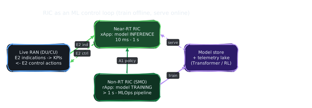
O-RAN is not just a networking topic — it is the substrate that makes AI-in-the-RAN deployable at all. Before the RIC, inserting a learned controller into a basestation meant convincing a vendor to ship it. The RIC turns "ML for the RAN" from a research slide into a runtime artifact: an xApp subscribes to E2 indications (KPIs, measurements), runs inference, and emits E2 control — a closed ML control loop on a live network.
The architecture's timescale separation maps directly onto an ML training/serving split: the non-RT RIC is where you collect data and train (offline, >1 s); the near-RT RIC is where you serve inference (online, 10 ms–1 s). This is structurally identical to a standard MLOps train-offline / serve-online pipeline — which is exactly why K8s/cloud-native experience transfers directly: the non-RT RIC and CU run as cloud-native workloads.
The xApp conflict problem (Round 3) is the cleanest motivation for reinforcement learning in this domain: a shared environment, multiple controllers, contested objectives — the textbook setup for multi-agent RL and constrained policy optimization.
Cross-links
AI · Transformer attention internals → the model class that powers RAN traffic prediction, a natural xApp input.
Papers · Shannon 1948 (channel capacity) → the information-theoretic ceiling the RU/DU physical layer is engineered against.
Papers · Attention Is All You Need → feeds the traffic-prediction and config-generation intersection nodes.
Pending intersection nodes this unblocks: ML for RAN anomaly detection (xApp), RL for network slicing & resource allocation, Transformer models for traffic prediction.
Open questions this raises
- What is the right conflict-resolution model when \(N\) xApps issue contradictory E2 control — priority hierarchy, constrained optimization, or learned arbitration (multi-agent RL)?
- Where exactly should a learned controller sit on the latency gradient? Some decisions (beamforming) want sub-ms, below the near-RT RIC's floor — does that force distilling the model down into the DU itself?
- Does software-PHY on commodity hardware net-save energy versus ASIC basestations once accelerator offload and pooling gain are accounted for? Under what cell-density regime does the answer flip?
- Should E2/A1/O1 interface semantics be their own KB node, or stay folded here?